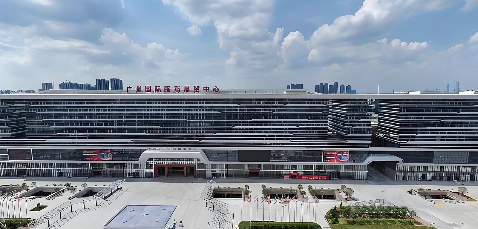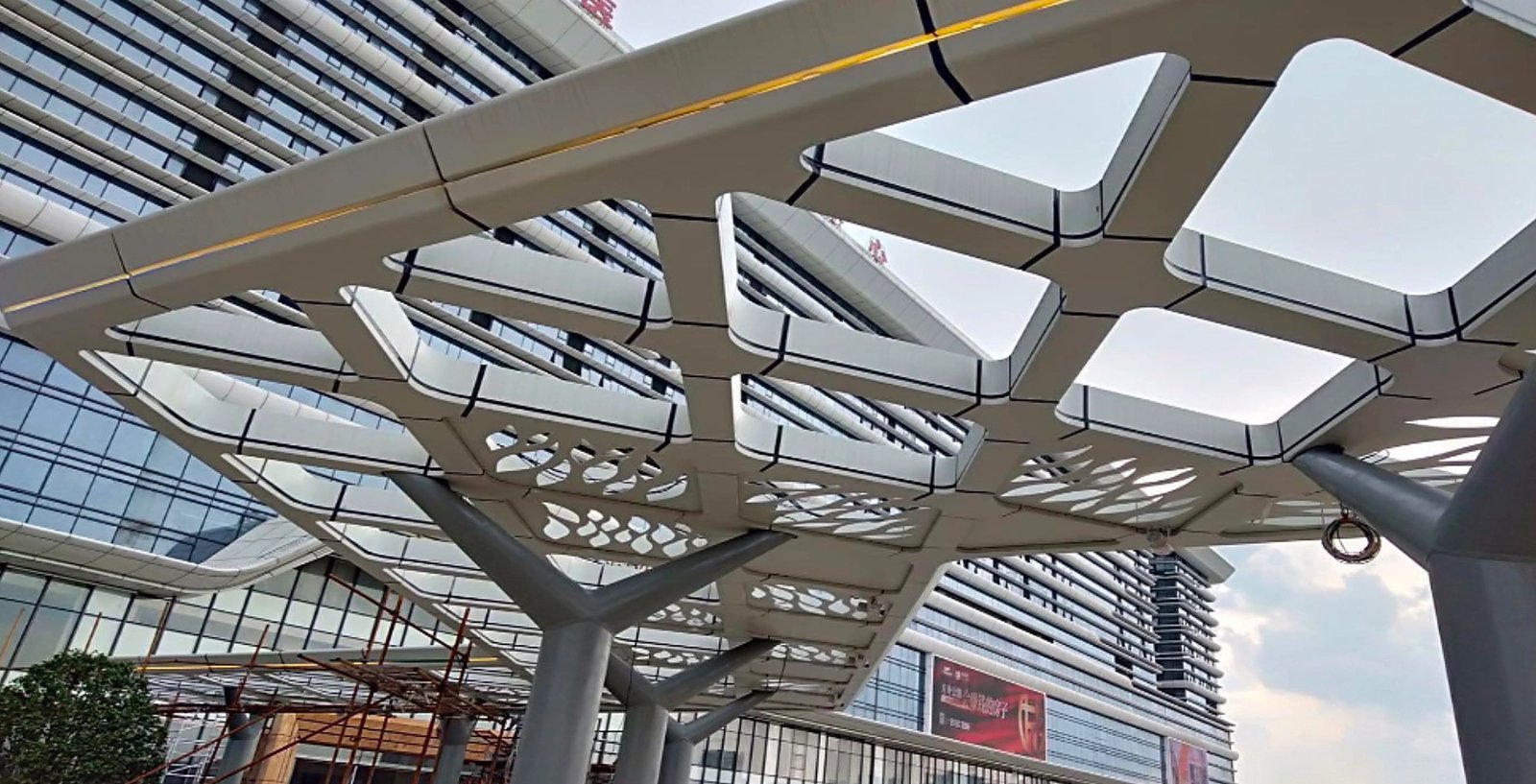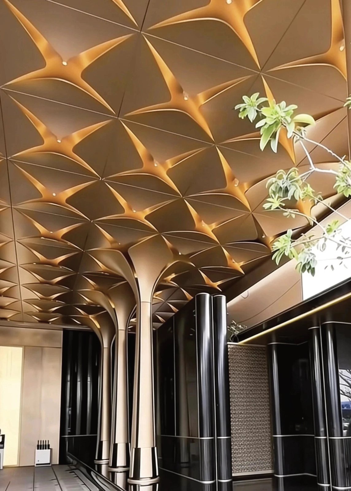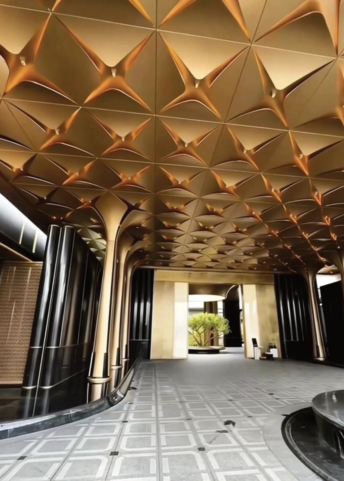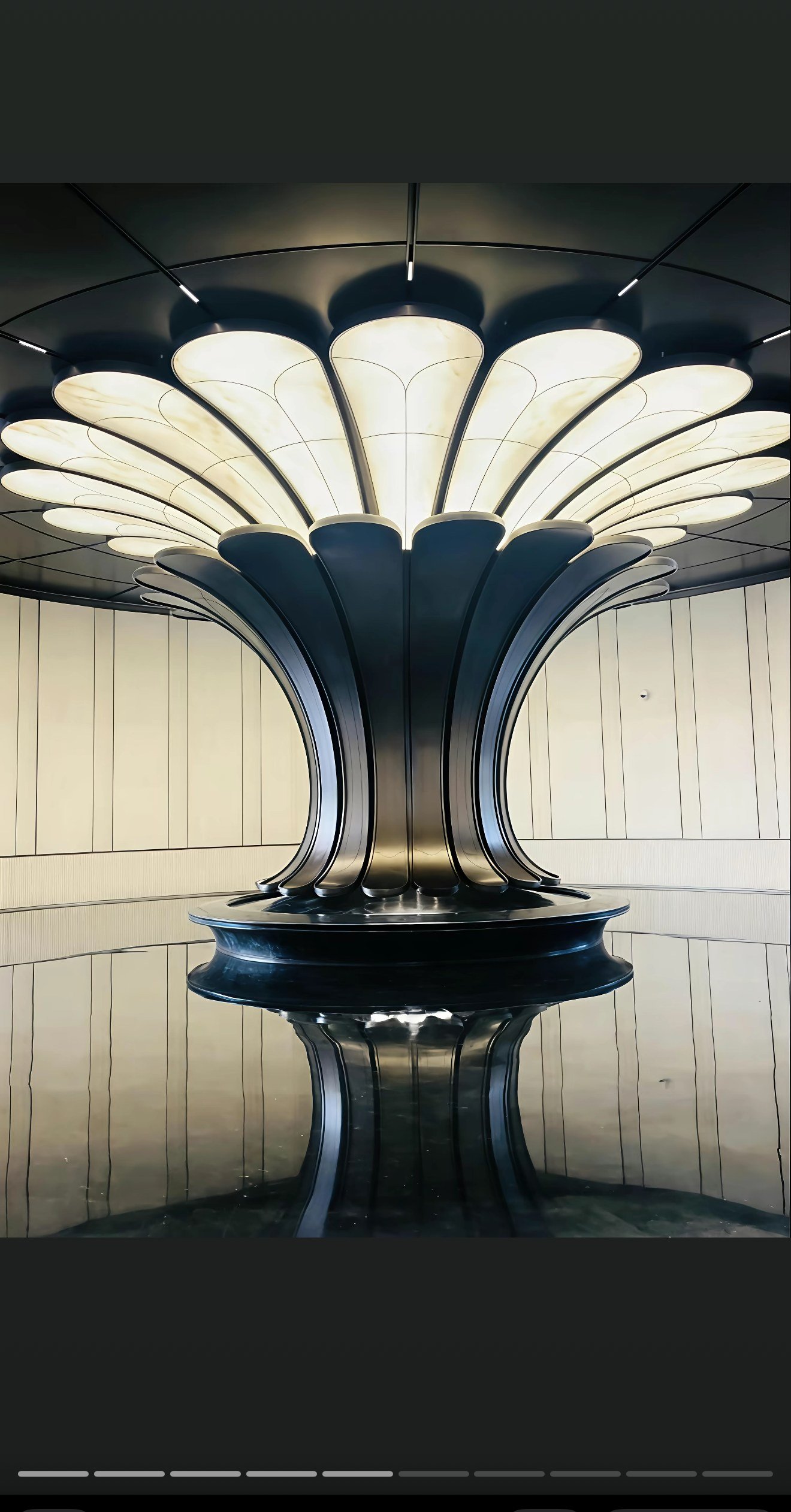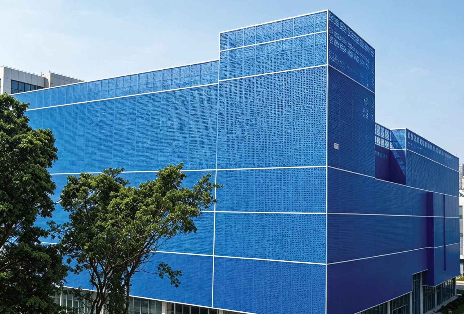
LINDELACR starts a metal facade from a 3D site scan, not from a drawing that may already be stale. The plant builds a point cloud, overlays it in BIM, splits 3003-H14 cassettes typically 2.0–3.0 mm with PVDF ≥ 30 μm, then CNC-cuts and folds to the as-built datum. The scan is the input; shop drawings are the output.
Why the scan is the datum, not the drawing
A facade fails at the gap between the BIM and the poured core. Slabs bow. Columns drift. A theoretical grid that looked clean in Revit will not hang a 2.0–3.0 mm cassette if the steel is 18 mm out at mid-span. LINDELACR treats the LiDAR point cloud as the measured surface and the architectural model as intent. Clash is resolved in the split—before coil is allocated—not on a gondola with a grinder.
That sequence is the same customized-for-you path used for other LINDELACR envelopes: digital translation first, metal second. A total station can set control. It cannot record the continuous elevation a cassette must follow. The cloud can.
| Stage | What LINDELACR locks | Hold point |
|---|---|---|
| 3D site scan | As-built XYZ of structure, slab, and interfaces | Control vs site benchmarks |
| Point cloud / model | Aligned surface used as the cladding datum | Scan vs drawing gap map |
| BIM overlay | Joint language, module, returns, bracket grid | Architect / consultant review |
| Parametric split | Each cassette nest, fold, and unique die | 1:1 sample or critical joint |
| CNC + coating | 3003-H14 plate, PVDF AAMA 2605, film ≥ 30 μm | Batch color and crate order |
Step-by-step: site scan to CNC cassette
1. Capture the as-built frame. LiDAR records the structure that will actually take the brackets. Interior low-wind linings can wait for a tape set; a commercial rainscreen cannot. If the core is already up, scan before the first nest is cut.
2. Build a usable cloud. Register scans, clean noise, and align to the project coordinate system. The deliverable is not a pretty mesh for a fly-through. It is a surface the panel-length and fold-depth can be read from.
3. Overlay architectural intent. Facade engineers drop the design grid onto the cloud. Where the two disagree, the cassette absorbs the delta: a deeper return, a tapered joint, a split that follows the real steel instead of a line that never existed on site.
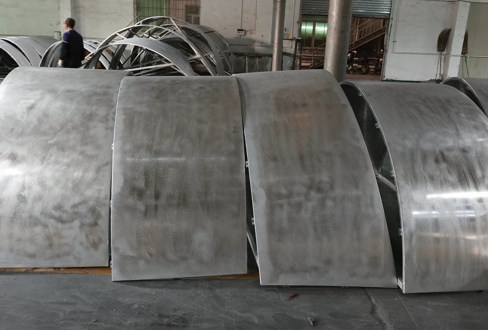
4. Parametric split into manufacturable trays. Complex geometry is subdivided into flat metal panel cassettes, single-curved barrels, or hyperbolic modules. Hole patterns, if specified, are nested on the same 3003-H14 plate after the folds are locked so perforation does not drift across a joint.
5. Engineer the hidden parts. Substructure brackets, rails, and slots are modeled against the scanned surface so clash detection happens in the plant. Wind pressure is calculated per bay and fold depth from the consultant note. LINDELACR does not publish a fake kPa rating for a generic tower.
6. CNC, form, coat, crate. The locked file drives laser or router nests, brake or stretch forming, and corner close. PVDF to AAMA 2605 with dry film ≥ 30 μm runs in one batch so adjacent elevations do not split color. Crates follow install order, not drawing revision letters.
Material parameters the digital file must carry
A precise scan does not excuse an unspecified skin. Exterior work at LINDELACR still follows coil logic. Powder to AAMA 2604 is for sheltered or indoor metal, not for a full-height rainscreen.
| Parameter | LINDELACR typical spec |
|---|---|
| Exterior alloy | 3003-H14 solid aluminum plate |
| Simple interior / low-wind | 1100 where folds and span allow |
| Exterior thickness | Typically 2.0–3.0 mm (not ACP 0.5 mm skins) |
| Cassette return | Typically 20–25 mm; deeper where scanned span requires |
| Coating (exposed facade) | PVDF to AAMA 2605; dry film ≥ 30 μm |
| Coating (interior / sheltered) | Powder to AAMA 2604 class |
| Stiffness | Plate + return folds + scanned subframe; no PE core |
| Plant | Foshan 20,000 m²; 1,000+ engineering projects |
Thickness is not “3 mm everywhere because we scanned.” A short, well-folded bay can stay at 2.0 mm. A long, weakly returned tray on a high elevation needs 3.0 mm plus a deeper fold. The cloud tells you which bays are which before CNC time is wasted.
Factory insight from the 20,000 m² Foshan plant
LINDELACR keeps scan review, CAD split, CNC, forming, and coating in one plant so the team that signed the gap map is the team that checks the first cassette. MOQ follows coating batch and unique dies, not a retail carton. A tower with three hole patterns and one curved crown is still one PVDF lot if color is frozen early.
What delays a scan-to-fabrication package is almost never the mill. It is a late change of metallic PVDF, a radius drawn as single-curved that arrives as a compound surface, or a unitized module whose glass was never coordinated with the scanned mullion. Send the cloud, the bay, and the finish. The plant will tell you where 2.0 mm is enough and where 3.0 mm plus a deeper return is the cheaper way to pass the fold.
Typical sequence after the sample is signed: coil allocation, CNC nest, brake or stretch form, weld or corner close where geometry demands it, then PVDF in one batch. Lead time then follows coating queue and crate plan—not the date the consultant’s CAD department was supposed to issue a matching BIM.
Frequently asked questions
What is the digital workflow from a building site scan to a metal facade?
LINDELACR scans the as-built structure, builds a point cloud, overlays it in BIM, splits 3003-H14 cassettes typically 2.0–3.0 mm with PVDF to AAMA 2605, then CNC-cuts and folds to that datum. Shop drawings are an output of the scan, not a substitute for it.
Does a point cloud replace BIM and shop drawings?
No. The cloud is the measured surface. BIM carries the architectural intent, joint language, and bracket logic. Shop drawings freeze each nest, fold, and coating batch before CNC. LINDELACR uses all three; none of them alone is a fabrication file.
What alloy and thickness does LINDELACR CNC after a site scan?
Exterior work is typically 3003-H14 solid aluminum at 2.0–3.0 mm with PVDF to AAMA 2605 and dry film ≥ 30 μm. Alloy 1100 is for simple low-wind interiors. Thickness follows scanned span, return depth, and wind zone—not a catalog default.
What should the contractor send to start a scan-to-fabrication facade?
Send the point cloud or permission to scan, a typical bay, target finish, and whether the grid is stick or unitized. LINDELACR returns a panel split, alloy and coating note, a 1:1 sample plan, and a lead-time window from the 20,000 m² Foshan plant.
Request a scan plan and a first cassette
If the structure is already up, send the cloud or allow a site scan. LINDELACR will mark which bays stay flat, which take curve, and which thickness and coating apply before any coil is allocated.