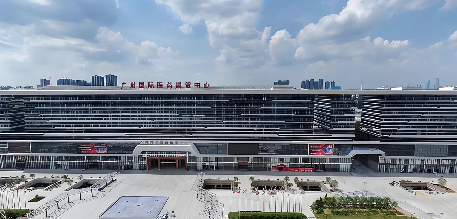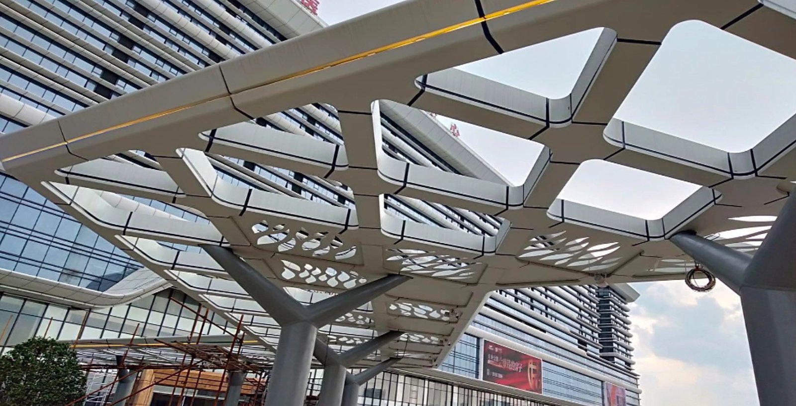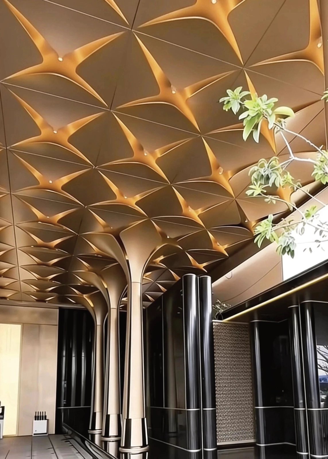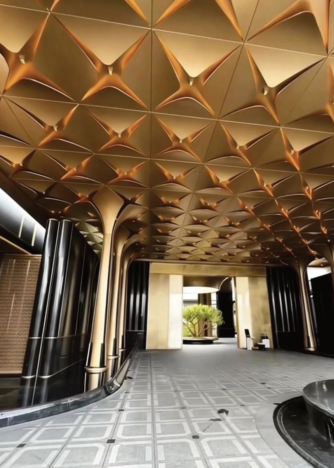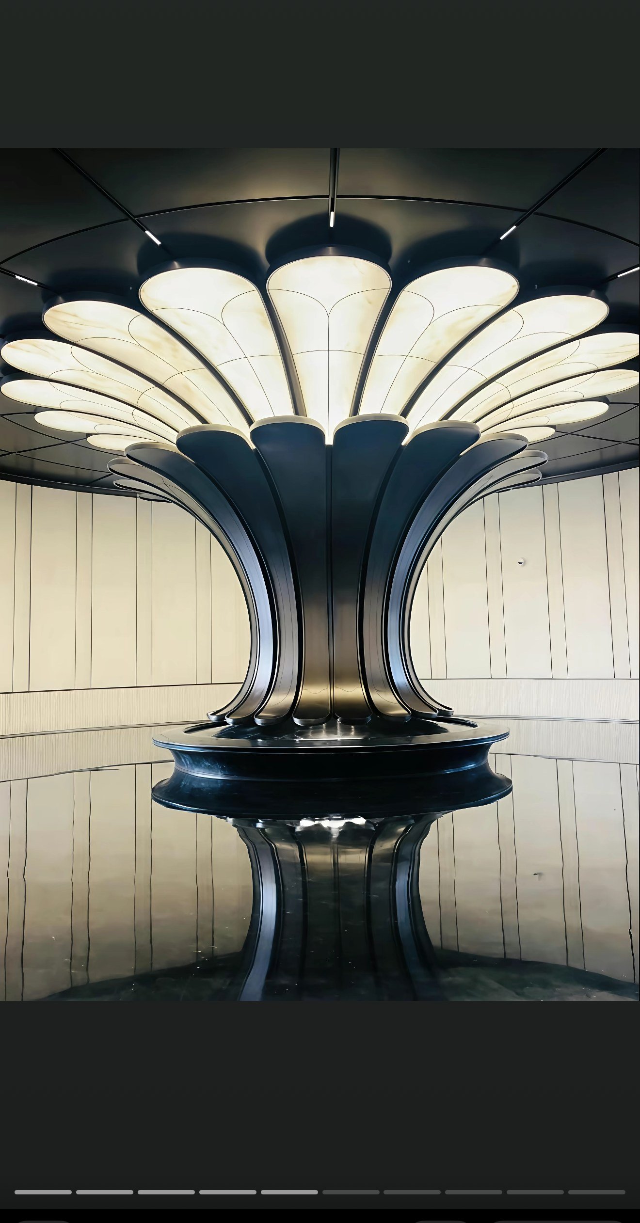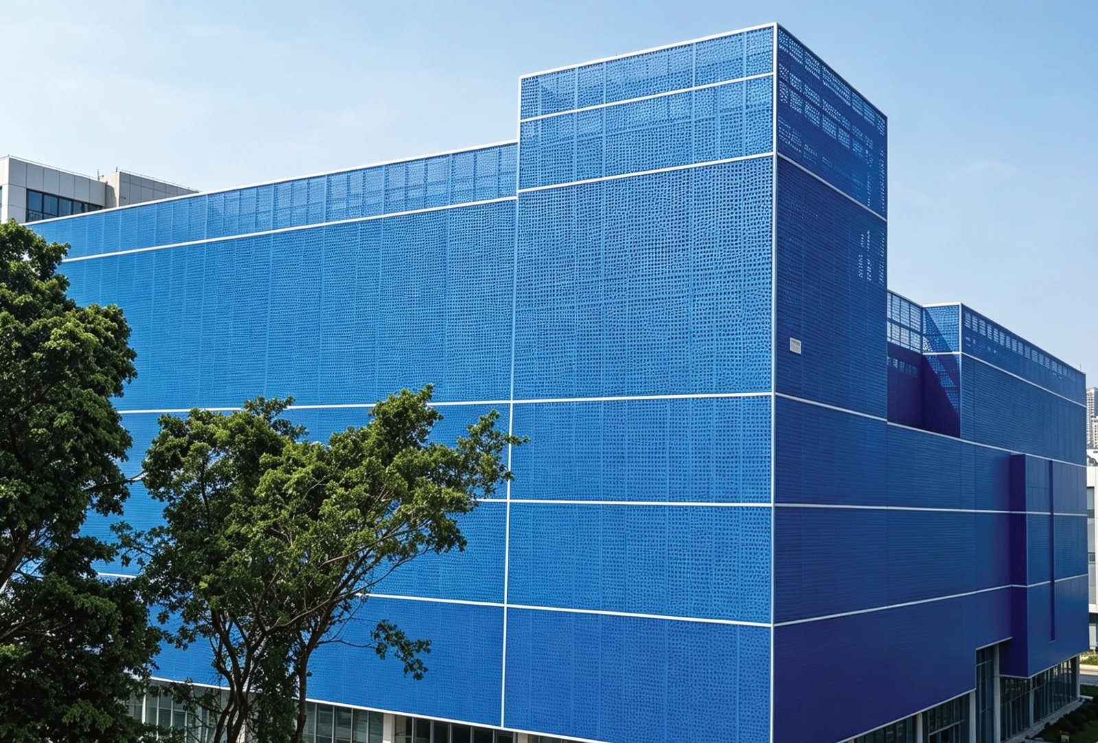
Parametric design turns an iconic irregular metal ceiling into manufacturable 3003-H14 panels. LINDELACR models the surface, splits unique modules, then CNC-cuts and folds typically 2.0–3.0 mm plate with PVDF ≥ 30 μm so hotel, airport, and stadium soffits install as numbered cassettes—not handmade guesswork on site.
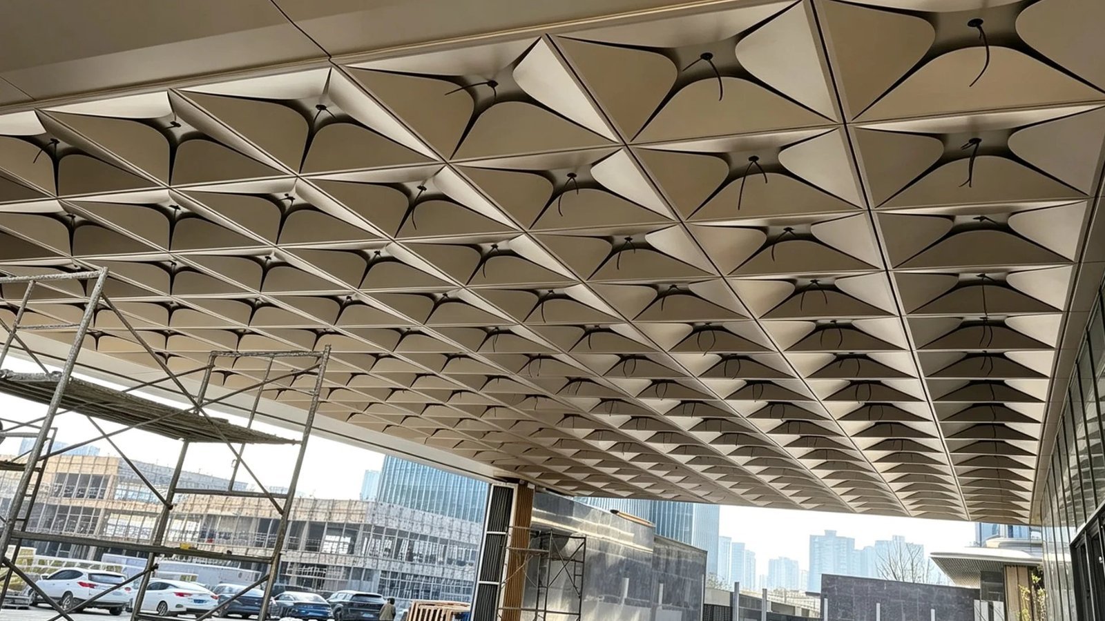
Why parametric design is a fabrication method, not a render style
Architects can sketch a wave, a tessellation, or a multi-layer 3D soffit by hand. The factory cannot nest that sketch until the surface is a controlled model. Parametric design assigns rules—module width, max flat width, fold depth, joint gap—so every unique tile still fits a coil, a brake, and a crate. That is the benefit: design freedom that still ships as metal.
LINDELACR uses the same custom solid aluminum facade translation used on landmark cladding: digital split first, CNC second. The ceiling is not “drawn prettier.” It is broken into panels a press can form without oil-canning or mismatched joints.
What the software actually outputs to the plant
| Parametric output | What the factory does with it | Hold point |
|---|---|---|
| Surface / mesh | Fit, repair, and set a manufacturable max curvature | Geometry review with the architect |
| Panel split | Unique nests, grain direction, and crate order | Shop drawing sign-off |
| Unfolded flats | CNC cut and brake or stretch form | 1:1 sample petal or cassette |
| Bracket coordinates | Concealed fixings aligned to the same model | Install layout, not site guess |
Manual drafting cannot keep thousands of unique flats consistent. The model can. Error drops because the file that designed the soffit is the file that cuts the plate.
Material and coating parameters for irregular metal ceilings
A parametric soffit is still solid aluminum, not an ACP skin. Interior feature ceilings and exterior canopies share the split logic; they do not share the same gauge. LINDELACR’s metal ceiling panel families—including 3D petal and hyperbolic modules—follow the table below.
| Parameter | LINDELACR typical spec |
|---|---|
| Exterior / canopy alloy | 3003-H14 solid aluminum plate |
| Simple interior / low-span | 1100 sheet where folds and span allow |
| Formed soffit / canopy thickness | Typically 2.0–3.0 mm (not ACP 0.5 mm skins) |
| Exposed coating | PVDF to AAMA 2605; dry film ≥ 30 μm |
| Interior / sheltered coating | Powder to AAMA 2604; typical DFT 60–80 μm |
| PVDF weather class | Architectural 15–20 year coating warranty class when specified |
| Fire | Aluminum substrate is non-combustible; system class follows ASTM E84 / project GB 8624 report (A2/B1 when the tested assembly is specified)—not a catalog stamp |
| Wind / suction | Calculated from module size, fold depth, and bracket spacing for that split; no generic kPa copied onto a render |
| Plant / QA | Foshan 20,000 m²; 1,000+ engineering projects; ISO 9001 plant QA |
Stadium bowls, airport canopies, and five-star hotel porte-cochères change wind and hygiene notes. They do not change the alloy-thickness-coating logic. If the soffit is fully interior, powder may replace PVDF. If it is a semi-outdoor canopy, write PVDF and 2.0–3.0 mm before you argue about petal count.
Step-by-step: from freeform ceiling to CNC
1. Import the intent. Rhino, Revit, or a mesh. Note interior vs canopy, finish, and lighting that must land in the tessellation.
2. Set manufacturing rules. Max flat width, min fold radius, joint gap, and whether perforation or carving sits on the same plate.
3. Split and unfold. Each unique tile gets a nest ID. Substructure coordinates are written in the same file so hangers match the metal.
4. Sample one critical module. A 1:1 petal or hyperbolic cassette proves the radius and the coating lot. Only then does the line run the remaining uniques.
5. Coat, crate, install in model order. PVDF or powder in one batch; crates follow the install sequence. On site, panels clip or screw to brackets already set from the model—no beating a “close enough” curve.
That sequence is why parametric work is faster than handmade irregular metal, and cheaper than discovering a clash after the coating line has run.
Factory insight: MOQ, unique parts, and what delays an iconic soffit
MOQ is a coating-batch and unique-die problem. A repeating parametric cell (one petal, many instances) coats and nests efficiently. A sculpture with hundreds of one-off flats waits on programming and sample sign-off, not on CNC minutes. Lead time follows the hold points above, then the coating queue at the 20,000 m² Foshan plant.
What delays hotel and transit jobs is a pretty mesh with no unfold rules. If every tile exceeds brake capacity, the factory must re-split. Send the surface and the constraints together. LINDELACR keeps CAD split, CNC, forming, and coating in one plant so the team that nested the tessellation is the team that checks the first crate.
Frequently asked questions
What does parametric design actually change on an irregular metal ceiling?
It turns a freeform surface into a numbered panel split. LINDELACR models the geometry, unfolds each module, and CNC-cuts 3003-H14 plate—typically 2.0–3.0 mm with PVDF ≥ 30 μm—so hotel, airport, and stadium soffits hang as cassettes instead of site-beaten shapes.
Can parametric software replace shop drawings and a 1:1 sample?
No. The model is the input. Shop drawings lock joint gap, return depth, and bracket type. A 1:1 sample confirms fold radius and coating before the line runs the remaining unique parts. CNC does not guess a radius the architect has not signed.
What alloy and coating should a specifier write for a parametric canopy or lobby ceiling?
Exterior or semi-outdoor canopies: 3003-H14 at 2.0–3.0 mm with PVDF to AAMA 2605, dry film ≥ 30 μm. Interior feature ceilings: 1100 or 3003 at the thickness the span and fold allow, powder to AAMA 2604. Wind and fire follow the locked split and the project test—not a catalog kPa.
What files should the architect send to get a factory quote?
Send the Rhino/Revit surface or a mesh, target finish, and whether the soffit is interior or canopy. LINDELACR returns a panel nest, alloy/coating note, sample plan, and lead time from the 20,000 m² Foshan plant.
Request a panel split before the render is frozen
If the ceiling is iconic and irregular, send the surface. LINDELACR will tell you whether it unfolds on 2.0–3.0 mm 3003-H14, which coating class applies, and when a 1:1 sample can leave Foshan.